|
|
| (8 intermediate revisions by 3 users not shown) |
| Line 1: |
Line 1: |
| __NOTOC__ | | __NOTOC__ |
| | [[Category:Spillways]] |
| ---- | | ---- |
| <!-- Delete any sections that are not necessary to your topic. Add pictures/sections as needed --> | | <!-- Delete any sections that are not necessary to your topic. Add pictures/sections as needed --> |
| | {{Picture |
| | |image= |
| | <!-- Add image file name (ex.image.jpg) --> |
| | uncontrolled.jpg |
| | |link= |
| | <!--https://en.wikipedia.org/wiki/Spillway--> |
| | |
| | |caption= |
| | <!-- Add picture caption --> |
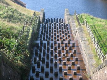
| | A stepped chute spillway in England. ([https://en.wikipedia.org/wiki/Spillway Wikipedia]) |
| | }} |
| | |
| “A controlled crest is one that includes gates which are used to control the flow; the uncontrolled crest is one unencumbered by gates”.<ref name="EM 1110-2-1603">[[Hydraulic Design of Spillways (EM 1110-2-1603) | EM 1110-2-1603 Hydraulic Design of Spillways, USACE, 1992]]</ref> | | “A controlled crest is one that includes gates which are used to control the flow; the uncontrolled crest is one unencumbered by gates”.<ref name="EM 1110-2-1603">[[Hydraulic Design of Spillways (EM 1110-2-1603) | EM 1110-2-1603 Hydraulic Design of Spillways, USACE, 1992]]</ref> |
|
| |
|
| “Common to all uncontrolled spillways that are not integral with a concrete dam (i.e., located away from the dam on or through abutments, or on or through reservoir rim) is that existing topography must provide adequate space without excessive excavation. Also, the existing topography must allow appropriate orientation (alignment of the spillway between the reservoir and downstream river or stream) of the conveyance feature and terminal structure. Additionally, economics will come into play for all uncontrolled spillways”.<ref name="DS14">[[Design Standards No. 14: Appurtenant Structures for Dams (Ch. 3: General Spillway Design Considerations) | Design Standards No. 14: Appurtenant Structures for Dams (Ch. 3: General Spillway Design Considerations), USBR, 2014]]</ref> | | “Common to all uncontrolled [[spillways]] that are not integral with a concrete dam (i.e., located away from the dam on or through abutments, or on or through reservoir rim) is that existing topography must provide adequate space without excessive excavation. Also, the existing topography must allow appropriate orientation (alignment of the spillway between the reservoir and downstream river or stream) of the conveyance feature and terminal structure. Additionally, economics will come into play for all uncontrolled spillways”.<ref name="DS14">[[Design Standards No. 14: Appurtenant Structures for Dams (Ch. 3: General Spillway Design Considerations) | Design Standards No. 14: Appurtenant Structures for Dams (Ch. 3: General Spillway Design Considerations), USBR, 2022]]</ref> |
|
| |
|
| ==Types of Uncontrolled Spillways== | | ==Types of Uncontrolled Spillways== |
| '''"Chute (open channel or trough) spillways -''' include baffled apron, grade control sill, stepped chute, and various shaped weirs:<ref name="DS14" />
| | *[[Chute Spillways]] |
| *"''Baffled apron spillway -'' This type of structure is suited for service, auxiliary, and emergency spillways. Baffled apron spillways provide crest control, conveyance, and energy dissipation in one structure. Primary considerations are associated with low to moderate hydraulic heads to ensure the baffles function properly and crest lengths are limited (i.e., significant cost increases as crest length increases). Additionally, this spillway may be practical in areas where there is limited space for a terminal structure such as a hydraulic jump stilling basin. Also, effectiveness (energy dissipation and discharge capacity) of baffled apron spillways can be adversely impacted by debris. An example of a baffled apron spillway is the service spillway at Reclamation’s Conconully Dam (embankment).<ref name="DS14" /> | | *[[Drop Spillways | Drop Inlet Spillways]] |
| *''"Grade control sill spillway -'' This type of control structure is primarily suited for auxiliary and emergency spillways; however, in some cases, it can function as a service spillway. A grade control sill is a less robust, minimal spillway typically limited to a vertical reinforced concrete wall (sill) that is placed in a trench through an excavated trapezoidal channel. The grade control sill can be constructed in both rock and soil foundations. The grade control sill spillway tends to have limited reserve discharge capacity, given channel armorment could be damaged or fail due to discharges that exceed design levels. Therefore, an important consideration is to limit potential erosion during spillway operation. In summary, this type of spillway should only be used on low head situations where the hydraulic drop (vertical dimension between the reservoir water surface and the downstream river or stream) can be effectively controlled, including limiting erosion potential. Examples of grade control sill spillways include the service spillway at Reclamation’s Crane Prairie Dam (embankment) and the emergency spillway at Reclamation’s Davis Creek Dam (embankment).<ref name="DS14" />
| | *[[Side-Channel Spillways]] |
| *''"Stepped chute spillway -'' This type of structure is suited for service and auxiliary spillways. Stepped spillways refer to the stepped chute portion of the spillway and have primarily been used with RCC dams, which take advantage of the RCC lift construction methods, resulting in offsets on the downstream dam face, creating the spillway steps. These steps can be formed or unformed RCC or capped with conventional concrete. A chute-type crest (flat), along with straight or curved ogee crests, are typically used in combination with stepped chutes. Other applications have involved incorporating both smooth flow surfaces and steps into a reinforced concrete spillway chute and RCC overtopping protection for an earth dam. A consideration for a stepped spillway involves the potential kinetic energy dissipation via the steps, which can reduce the size and type of the terminal structure. However, the kinetic energy dissipation potential may be reduced as flow depth (relative to the step size) increases (due to skimming flows). Also, consideration should be given to evaluating the cavitation potential. Examples of stepped spillways include the service spillway at Maricopa Water District’s Camp Dyer Diversion Dam (concrete), the auxiliary spillway (Joint Federal Project) at Reclamation’s Folsom Dam (composite), and the service spillway at Reclamation’s Upper Stillwater Dam (concrete). <ref name="DS14" />
| | *[[Free Overfall Spillways]] |
| *''"Various shaped weirs -'' This type of structure is suitable for service, auxiliary, and emergency spillways. The hydraulic control is established by various shaped weirs ranging from broad-crested to sharp-crested weirs to no weir (flat bottom or sloping channel). Various shaped weir control structures are not as efficient as an ogee crest control structure, but they still tend to have sizable reserve discharge capacity (i.e., increased discharge due to elevated reservoir water surface). Also, various shaped weir control structures are relatively free of operation and maintenance issues. This type of spillway is applicable to both concrete and embankment dams and can be gated or ungated. Examples of various shaped weir spillways include the auxiliary spillway at Reclamation’s Deerfield Dam (embankment) and the service spillway at Reclamation’s Lost Lake Dam (embankment).<ref name="DS14" />
| |
| | |
| '''"Drop inlet spillways -''' including morning glory (shaft) and other drop inlet control structures – These types of control structures are suited for service and auxiliary spillways.<ref name="DS14" />
| |
| *''"Morning glory control structures -'' This structure is a type of drop inlet spillway. This type of control structure should be considered when there is very limited space and there is adequate rock foundation. The morning glory spillway (sometimes referred to as a “shaft” spillway) has the potential of small to moderate discharge capacity and is used with conduit and tunnel conveyance features. This type of spillway is applicable to concrete, embankment, and composite dams, and it can be gated or ungated. As hydraulic head on the crest increases, the flow transitions from crest control to throat (orifice) control and, in some cases, to pipe (pressure) control, resulting in reduced discharge efficiency. Morning glory spillways are typically designed to only operate in the crest control range. Larger discharges could result in adverse hydraulics in the downstream conduit or tunnel (slug and/or pressure flow). Also, this spillway type may be vulnerable to debris plugging. If heavy debris loads are anticipated during flood events, consider defensive measures to protect the control structure (such as debris booms) or consider other types of spillway control structures. Examples of morning glory spillways include the service spillways at Reclamation’s Hungry Horse Dam (concrete), Ridgway Dam (embankment), Trinity Dam (embankment), and Owyhee Dam (concrete).<ref name="DS14" /> | |
| *''"Other drop inlet spillways -'' This type of spillway is most applicable where there is a small amount of space to locate the control structure, there is adequate rock foundation, and the conveyance feature will be a conduit or tunnel. This type of spillway is applicable to concrete, embankment, and composite dams, and it can be gated or ungated. This spillway is very similar to an outlet works intake tower and may be in combination with an outlet works. This spillway has the potential of small discharge capacity. Larger discharges than design levels can result in hydraulic control shifts (crest to orifice and/or orifice to pipe control) that could result in adverse hydraulics in the downstream conduit or tunnel (slug and/or pressure flow). Also, this spillway type may be vulnerable to debris plugging. If heavy debris loads are anticipated during flood events, consider defensive measures to protect the control structure (such as debris booms) or consider other types of spillway control structures. Examples of other drop inlet spillways include the service spillways at Reclamation’s B.F. Sisk Dam (embankment) and Lake Sherburne Dam (embankment).<ref name="DS14" /> | |
| | |
| '''"Double side-channel (bathtub) and side-channel spillways -''' These types of control structures are suited for service and auxiliary spillways. Bathtub and side-channel control structures should be considered where there is limited space (insufficient space to accommodate a straight or curved ogee crest control structure) and there is adequate rock foundation. Also, these types of spillways are applicable to concrete, embankment, and composite dams, and they can be gated or ungated. These types of control structures have the potential for large discharge capacity and can be used with conveyance features including chutes, conduits, and tunnels. However, larger discharges than design levels can result in suppression and/or submergence of the crest and a reduction in the effective crest length. As the effective crest length is reduced, the spillway becomes less efficient (i.e., higher hydraulic heads may not significantly increase the discharge). Larger discharges could lead to downstream “throat” hydraulic control and adverse hydraulics, such as overtopping chute walls or pressurizing conduits or tunnels. A typical consideration is that a hydraulic jump occurs in the control structure before the flow enters the downstream conveyance feature (chute, conduit, or tunnel). This is done to establish a hydraulic control just downstream of the control structure, which facilitates the flow path down the conveyance feature (i.e., minimizes unstable flow in the conveyance features such as standing or cross waves). Examples of bathtub spillways include the service spillways at Reclamation’s Island Park Dam (embankment) and Fontenelle Dam (embankment). Examples of side-channel spillways include the service spillways at Reclamation’s Big Sandy Dam (embankment) and Paonia Dam (embankment).<ref name="DS14" />
| |
| | |
| '''"Free overfall spillway including ogee crest, various shaped weirs, and straight drop control structures -''' These types of spillways are structures where the flow drops freely from the crest. These types of control structures are suited for service, auxiliary, and emergency spillways.<ref name="DS14" />
| |
| *''"Ogee crest control structures and various shaped weirs control structures -'' This type of control structure is suited to a concrete arch dam or to a crest that has a steep downstream face. This spillway can be gated or ungated. Flows may be free discharging (as is the case with a sharp-crested weir), or the flows may be supported along a narrow section of crest (such as an ogee crest that immediately terminates at a lip or flip that directs the free jet downstream). For free overfall spillways, the flow undernappe should be ventilated sufficiently to prevent a pulsating, fluctuating jet. Of note, where no artificial protection (such as an armored plunge pool) is provided, scour of the streambeds may occur and form (erode) a plunge pool. Where erosion cannot be tolerated or needs to be controlled, an artificial pool can be constructed. Examples of free overfall (ogee crest) spillways are the service spillways at Reclamation’s Crystal Dam (concrete) and Pueblo Dam (composite). Example of free overflow (various shaped weir) are the modified dam crests of Reclamation’s Buffalo Bill Dam (concrete) and Gibson Dam (concrete), which serve as auxiliary spillways.<ref name="DS14" />
| |
| **''"Straight ogee control structures -'' This type of control structure tends to have considerable reserve discharge capacity (i.e., increased discharge due to elevated RWS). Also, straight ogee control structures are relatively free of operation and maintenance issues. This type of spillway is applicable to concrete, embankment, and composite dams, and it can be gated or ungated. Examples of straight ogee spillways include the service spillways at Reclamation’s Scofield Dam (embankment) and Sugar Pine Dam (embankment).<ref name="DS14" />
| |
| **"''Curved ogee control structures -'' This type of control structure is influenced by similar considerations as the straight ogee control structure. In addition, a curved control structure lends itself to rapid narrowing of the downstream conveyance feature, which helps to minimize excavation or allow transition to a tunnel conveyance feature. These types of spillways are applicable to concrete, embankment, and composite dams, and they can be gated or ungated. Examples of curved ogee spillways include the service spillways at Reclamation’s Casitas Dam (embankment) and Meeks Cabin Dam (embankment).<ref name="DS14" />
| |
| *''"Straight drop control structures -'' This type of control structure can be very effective over a wide range of tailwater depths and is applicable for low embankment dams. It consists principally of a straight wall (sharp crested) weir set at the upper end of a rectangular chute section, with an apron placed below streambed, and includes floor blocks and an end sill. This type of spillway is not applicable to high drops (large hydraulic head) on unstable foundations. Ordinarily, this spillway type should be limited to no more than a hydraulic head drop of 20 feet (distance between the reservoir and the tailwater surfaces). Examples of the free-flow (straight drop) spillway are the emergency spillway at Reclamation’s Trial Lake Dam (embankment) and the service spillway at the National Park Service’s PEEC’s Dam (embankment).<ref name="DS14" />
| |
| | |
| ''"Labyrinth weir spillways -'' These types of control structures are suited for service and auxiliary spillways. The spillway provides added crest length for a given total crest width, so less hydraulic head (than a straight weir) is needed to pass a given discharge. The additional crest length is obtained by a series of trapezoidal, rectangular, or triangular walls within the total width. These walls are thin and cantilevered, vertical on the upstream face and steeply sloped on the downstream slope. Labyrinth weir control structures can be considered where space is limited, large discharge associated with small hydraulic head is needed, and there is adequate foundation (typically rock). However, larger hydraulic head than design levels can result in reduced discharge efficiencies (i.e., acting more like a broad-crested weir with reduced effective crest length rather than a sharp-crested weir with extended crest length). These types of control structures are used with chute conveyance features. An example of a labyrinth weir spillway is the service spillway at the New Mexico Interstate Stream Commission’s Ute Dam (embankment).<ref name="DS14" />
| |
| | |
| ''"Ogee crest spillways include both straight and curved control structures -'' These types of control structures are suited for service, auxiliary, and emergency spillways.<ref name="DS14" />
| |
| *''"Straight ogee control structures -'' This type of control structure tends to have considerable reserve discharge capacity (i.e., increased discharge due to elevated reservoir water surface). Also, straight ogee control structures are relatively free of operation and maintenance issues. This type of spillway is applicable to concrete, embankment, and composite dams, and it can be gated or ungated. Examples of straight ogee spillways include the service spillways at Reclamation’s Scofield Dam (embankment) and Sugar Pine Dam (embankment).<ref name="DS14" />
| |
| *''"Curved ogee control structures -'' This type of control structure is influenced by similar considerations as the straight ogee control structure. In addition, a curved control structure lends itself to rapid narrowing of the downstream conveyance feature, which helps to minimize excavation or allow transition to a tunnel conveyance feature. These types of spillways are applicable to concrete, embankment, and composite dams, and they can be gated or ungated. Examples of curved ogee spillways include the service spillways at Reclamation’s Casitas Dam (embankment) and Meeks Cabin Dam (embankment).<ref name="DS14" />
| |
| | |
| ''"Orifice headwall spillways -'' These types of control structures are suited for service, auxiliary, and emergency spillways. A variation of the orifice spillway, which has been successfully used in modifying existing straight ogee spillways, involves the construction of a headwall above the ogee crest or various shaped weirs. The opening between the bottom of the headwall and the crest creates orifice control during elevated reservoir water surfaces. This type of modification has been very effective in limiting maximum spillway discharges to no more than the original design discharge capacity even with reservoir water surfaces greater than the original design maximum reservoir water surface. Also, these types of spillways are applicable to concrete, embankment, and composite dams. An example includes the service spillway at Reclamation’s Glendo Dam.<ref name="DS14" />
| |
| | |
| ''"Overtopping protection structures -'' These types of structures are suited for auxiliary and emergency spillways. Overtopping protection should only be considered if there are no other technically viable and cost-effective options to safely pass flood events. Overtopping protection can apply to concrete, embankment, and composite dams. Overtopping protection generally applies when there is some combination of remote chance of operation, physical or environmental constraints of constructing other alternatives, and/or prohibitive cost of other alternatives. Overtopping protection applications could include the following:<ref name="DS14" />
| |
| *"For embankment dams or embankment portion of composite dams: Overtopping protection is placed over the embankment and at the downstream toe of the dam to limit erosion during overtopping. Overtopping protection materials include RCC, conventional or mass concrete, precast concrete blocks, gabions, riprap, turf reinforcement mats, vegetative cover, flow-through rockfill, reinforced rockfill, geomembranes, geocells, and fabric-formed concrete. <ref name="DS14" />
| |
| *"For concrete dams or concrete portion of composite dams: Overtopping protection is typically placed on the abutments and at the downstream toe of the dam where erosion might compromise the dam foundation. Overtopping protection materials include RCC, conventional or mass concrete, foundation and abutment reinforcement, abutment, and plunge pool erosion protection.<ref name="DS14" />
| |
| | |
| ''"Tunnel inlet spillways -'' These types of control structures are suited for service and auxiliary spillways. The tunnel inlet spillways are applicable to situations where there is a small amount of space to locate the control structure, there is adequate rock foundation, and the conveyance feature will be a tunnel. These types of spillways are applicable to concrete, embankment, and composite dams, and they can be gated or ungated. The control structure will include a geometry transition from a crest structure to a circular tunnel section. The tunnel inlet control structures have included ogee crests, side-channel and bathtub features, and various shaped weirs. Also, this spillway has the potential of moderate to large discharge capacity. Larger discharges than design levels can result in hydraulic control shifts (crest to orifice and/or orifice to pipe control) that could result in adverse hydraulics in the downstream tunnel (slug and/or pressure flow). Examples of tunnel inlet spillways include the service spillways at Reclamation’s Kortes Dam (concrete) and Twitchell Dam (embankment).<ref name="DS14" />
| |
|
| |
|
| ''"Culvert spillways -'' These types of control structures are suited for service, auxiliary, and emergency spillways. The culvert spillways are most applicable as appurtenant structures for low head dams (i.e., hydraulic head is 25 feet or less). Although there is simplicity and economy of construction, there are some significant potential concerns that must be fully addressed. These concerns include: (1) under certain conditions, the culvert may operate as a siphon, which can lead to adverse hydraulics (sudden surges and stoppages of flow, outflow exceeds inflow if operation shifts from inlet control to exit control, and significant vibrations that could damage the culvert and its foundation); (2) culverts on steep slopes flowing full can lead to negative pressures along the boundaries of the culvert, resulting in potential cavitation issues; and (3) if there are cracks or joints in low pressure areas, there is a possibility of drawing in soils surrounding the culvert. A culvert spillway does not have sizable reserve discharge capacity (i.e., increased discharge due to elevated reservoir water surface). Also, a culvert spillway is more susceptible to debris blockage. Examples of culvert spillways include the service spillway at Reclamation’s Martinez Dam (embankment) and the emergency spillway at Reclamation’s Weber Basin Comber Dam (embankment)”.<ref name="DS14" />
| | <noautolinks>==Best Practices Resources==</noautolinks> |
| | {{Document Icon}} [[Design Standards No. 14: Appurtenant Structures for Dams (Ch. 3: General Spillway Design Considerations) | Design Standards No. 14: Appurtenant Structures for Dams (Ch. 3: General Spillway Design Considerations), USBR]] |
| | {{Document Icon}} [[National Engineering Handbook: Chapter 50 - Earth Spillway Design | National Engineering Handbook: Chapter 50 - Earth Spillway Design, NRCS]] |
| | {{Document Icon}} [[Hydraulic Design of Spillways (EM 1110-2-1603) | Hydraulic Design of Spillways (EM 1110-2-1603), USACE]] |
|
| |
|
| ==Best Practices Resources==
| |
| {{Document Icon}}[[Hydraulic Design of Spillways (EM 1110-2-1603)|Hydraulic Design of Spillways (EM 1110-2-1603) (U.S. Army Corps of Engineers)]]
| |
| {{Document Icon}}[[Design Standards No. 14: Appurtenant Structures for Dams (Ch. 3: General Spillway Design Considerations)|Design Standards No. 14: Appurtenant Structures for Dams (Ch. 3: General Spillway Design Considerations) (Bureau of Reclamation]]
| |
| {{Document Icon}}[[Dams National Engineering Handbook: Chapter 50- Earth Spillway Design|Dams National Engineering Handbook: Chapter 50- Earth Spillway Design (Natural Resources Conservation Service)]]
| |
| ==Trainings== | | ==Trainings== |
| {{Video Icon}}[[On-Demand Webinar: Introduction to Earth Spillway Design and Evaluation]] | | {{Video Icon}} [[On-Demand Webinar: Introduction to Earth Spillway Design and Evaluation]] |
| {{Video Icon}}[[On-Demand Webinar: Dam Safety with 3D Weirs]] | | {{Video Icon}} [[On-Demand Webinar: Dam Safety with 3D Weirs]] |
| {{Video Icon}}[[On-Demand Webinar: Hydraulic Design of Labyrinth Weirs]] | | {{Video Icon}} [[On-Demand Webinar: Hydraulic Design of Labyrinth Weirs]] |
|
| |
|
|
| |
|